What changes the pressure at the tool
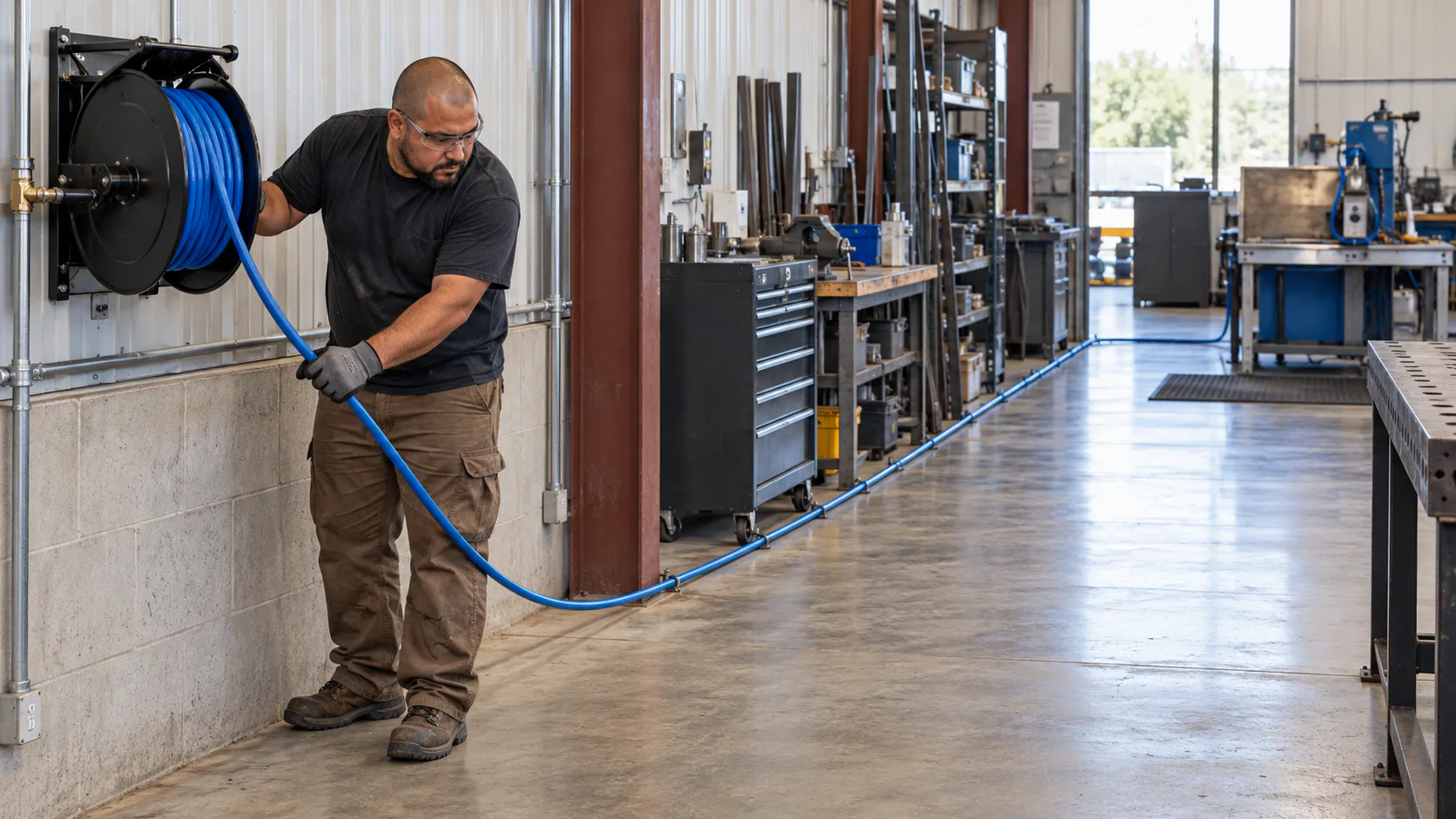
Pressure falls as compressed air moves through a hose, tube, pipe, fitting, filter, or regulator. Friction against the inside wall and restrictions in the flow path create the loss.
Three variables have an especially visible effect:
- Length: a longer run produces more pressure loss when the other conditions stay the same.
- Inside diameter: a smaller opening raises velocity and pressure drop.
- Airflow: a tool demanding more air produces a larger drop through the same line.
The pressure shown at the compressor is therefore not necessarily the pressure available at the tool while air is flowing.
Hose pressure-loss lookup at 90 PSI
Gates, a hose manufacturer, publishes an online air-flow calculator for its hoses. We entered a gauge pressure of 90 PSI and recorded the total pressure loss it returned for three common inside diameters. The calculator states that its equations rest on assumptions and average conditions and should be used as a guide only.
25 feet of hose, 90 PSI gauge pressure
| Airflow | 1/4-inch ID | 3/8-inch ID | 1/2-inch ID |
|---|---|---|---|
| 2 SCFM | 0.45 PSI | 0.05 PSI | 0.01 PSI |
| 4 SCFM | 1.82 PSI | 0.22 PSI | 0.05 PSI |
| 6 SCFM | 4.09 PSI | 0.48 PSI | 0.11 PSI |
| 8 SCFM | 7.26 PSI | 0.86 PSI | 0.19 PSI |
| 10 SCFM | 11.35 PSI | 1.35 PSI | 0.30 PSI |
50 feet of hose, 90 PSI gauge pressure
| Airflow | 1/4-inch ID | 3/8-inch ID | 1/2-inch ID |
|---|---|---|---|
| 2 SCFM | 0.91 PSI | 0.11 PSI | 0.02 PSI |
| 4 SCFM | 3.63 PSI | 0.43 PSI | 0.09 PSI |
| 6 SCFM | 8.17 PSI | 0.97 PSI | 0.21 PSI |
| 8 SCFM | 14.52 PSI | 1.72 PSI | 0.38 PSI |
| 10 SCFM | 22.70 PSI | 2.69 PSI | 0.59 PSI |
Conditions: Gates air-flow calculator outputs for the stated hose inside diameter, length, airflow and 90 PSI gauge pressure, retrieved 2026-10-26. The figures describe straight hose only. Couplers, regulators, filters, bends and the tool's own inlet add further loss that the tables do not include.
Three patterns stand out:
- Doubling the airflow roughly quadruples the loss. Through 50 feet of 1/4-inch hose, 4 SCFM loses 3.63 PSI and 8 SCFM loses 14.52 PSI.
- Doubling the length doubles the loss. Every 50-foot value is twice the 25-foot value at the same airflow. Reelcraft's hose bulletin states the same rule: pressure loss is directly proportional to length.
- A larger inside diameter changes this example sharply. At 8 SCFM over 50 feet, moving from 1/4-inch to 3/8-inch inside diameter cuts the calculated loss from 14.52 PSI to 1.72 PSI.
How to read a cell for your own setup
Find the tool's published airflow on its manual or product page, then read across at the hose length and inside diameter you actually use. Subtract the result from the regulated pressure to estimate what reaches the end of the hose while the tool is running.
Reelcraft's bulletin gives a working limit to compare against: when the tool's minimum efficient operating pressure is not available, it recommends that hose pressure drop not exceed 10 PSI at a 90 PSI inlet. In the 50-foot table, the calculated loss through 1/4-inch hose crosses 10 PSI somewhere between 6 and 8 SCFM, while the 3/8-inch hose stays below 3 PSI at every listed flow. Reelcraft's own worked example applies the same test to a production paint spray gun needing 8 CFM at 80 to 100 PSI: the 1/4-inch hose reaches a 15 PSI loss on its 50-foot curve, so Reelcraft rejects it and selects 3/8-inch hose. Reelcraft also says tool manufacturers' recommendations should govern.
A worked example from the table: a tool publishing 6 SCFM on 50 feet of 1/4-inch hose loses about 8.17 PSI in the hose alone. On 25 feet of the same hose, the loss is about 4.09 PSI. On 50 feet of 3/8-inch hose, it is about 0.97 PSI. Those are calculator estimates for the hose only, before fittings.
Published references do not agree exactly
Different hose references use different methods, so the same setup can produce different numbers. Comparing three of them shows how far to trust a single cell.
| Reference | Hose and conditions | Published loss | Gates comparison |
|---|---|---|---|
| Reelcraft bulletin (Rubber Manufacturers Association curve) | 1/4-inch ID, 50 ft, 8 CFM, 90 PSI inlet | 15 PSI | 14.52 PSI |
| Reelcraft bulletin | 1/2-inch ID, 50 ft, about 50 CFM, 90 PSI inlet | 10 PSI | 14.84 PSI |
| Binks and DeVilbiss hose chart | 1/2-inch ID, 100 ft, 40 CFM, inlet pressure not stated | 17.5 PSI | 18.99 PSI using a 90 PSI input |
The quarter-inch example agrees closely. The half-inch examples differ by several PSI. Reelcraft calls its curves a guide because hose inside-diameter tolerance, fittings and orifice restrictions all change actual discharge, and its bulletin adds that temperature can change friction loss by 20 percent and bends can increase it by 50 percent. Binks and DeVilbiss say a rough inner tube can raise pressure drop by up to 50 percent. Treat any table as an estimate, then confirm by measuring pressure at the tool while it runs.
Why inside diameter matters so much
EXAIR publishes a pressure-drop equation in which inside diameter appears to the fifth power in the denominator. With the other variables held constant, halving the inside diameter increases the calculated pressure drop by a factor of 32.
The same source explains a related flow effect. At equal air velocity, halving the inside diameter reduces flow to 25 percent. To move the same flow through that smaller opening, velocity would have to rise fourfold. That is why a small bore in one fitting can matter even when the hose itself is larger.
Use actual inside diameter, not the nominal thread or product size, when a source provides it.
A 3/8-inch hose is not the same as 3/8-inch tube
EXAIR explains that compressed-air hose is measured by inside diameter while tube is measured by outside diameter. In its comparison:
- 3/8-inch hose has a 0.375-inch inside diameter.
- 3/8-inch tube has a 0.25-inch inside diameter.
Using its pressure-drop relationship, EXAIR calculates that the tube produces 7.6 times the pressure drop of the hose under the example's other fixed conditions.
Nominal size can also hide close matches across different materials. EXAIR lists a quarter-inch NPT Schedule 40 pipe at 0.364 inch inside and a three-eighths-inch compressed-air hose at 0.375 inch inside. The labels differ, but the actual openings are close.
EXAIR consequently recommends moving one size larger than the recommended pipe size when compressed-air hose is used. That is EXAIR's sizing recommendation for the conditions it discusses, not a substitute for the tool and hose manufacturers' instructions.
Quick connects and other restrictions
A hose can be correctly sized while a fitting, filter, regulator, or valve becomes the narrowest part of the path.
EXAIR shows one quarter-inch quick-disconnect example whose internal opening measures close to 0.192 inch, much smaller than its nominal NPT connection. In EXAIR's Super Air Knife example, that fitting cannot support the required volume and causes a pressure drop.
The 0.192-inch measurement belongs to the specific fitting shown in that source. Quick connects with the same nominal connection can have different internal geometries, so inspect the published bore or flow rating for the actual fitting rather than assigning this measurement to the whole category.
Reelcraft also cautions that its hose curves are guides. Hose inside-diameter tolerance, fitting type, and orifice restrictions affect actual discharge. Its bulletin says temperature can change friction loss by 20 percent and bends can increase it by 50 percent.
A practical diagnostic sequence
When a pneumatic tool feels weak at the end of a line, check the complete flow path:
- Find the tool's published airflow and required operating pressure.
- Measure the hose run and record the hose's actual inside diameter.
- Check the bore or flow rating of quick connects, filters, regulators, swivels, and valves.
- Look for unnecessary bends, kinks, damaged hose, and undersized sections.
- Measure pressure at the tool while it is flowing air, following the manufacturer's test procedure.
- Compare the result with a pressure-drop table or curve for the actual hose or pipe material and size.
Do not compensate for a restrictive line by raising pressure beyond the tool, hose, fitting, or compressor limits. Follow the manufacturers' instructions and have a qualified person review permanent plumbing, electrical work, or a multi-tool installation.
The same-pressure comparison guide explains how to keep tool demand and compressor output conditions aligned. You can also use the matcher for exact CFM-labelled records before accounting for the downstream hose and fittings.
Sources checked
- Air Flow Calculator | Gates, outputs retrieved 2026-10-26.
- Pressure Drop / Flow Rate Charts and Graphs | Reelcraft, checked 2026-10-26.
- Hose, Connections and Assemblies: Understanding Pressure Drop | Binks and DeVilbiss accessories guide, hosted by Clemtex, checked 2026-10-26.
- How to Calculate and Avoid Compressed Air Pressure Drop | EXAIR, checked 2026-10-07.
- Pipe sizing articles | EXAIR, checked 2026-10-07.
Calculator outputs, tables and curves apply only to their stated conditions. Recheck current specifications for the exact hose, fittings, tool and compressor before changing a system.